
Use one independent signal for each area and alarm level you need to identify. With Y402-41-L, four single-input slaves map to four separate outputs on one master. One system covers four areas for one alarm level; additional systems carry more levels or serve more areas.
This example gives every alarm point its own wireless module, so dispersed buttons do not need long signal cables back to the control room. Each module still needs local power. Follow the four-area layout below, then expand it for multiple alarm levels, more areas or a route that needs two radio segments.

Start with four areas and one alarm level
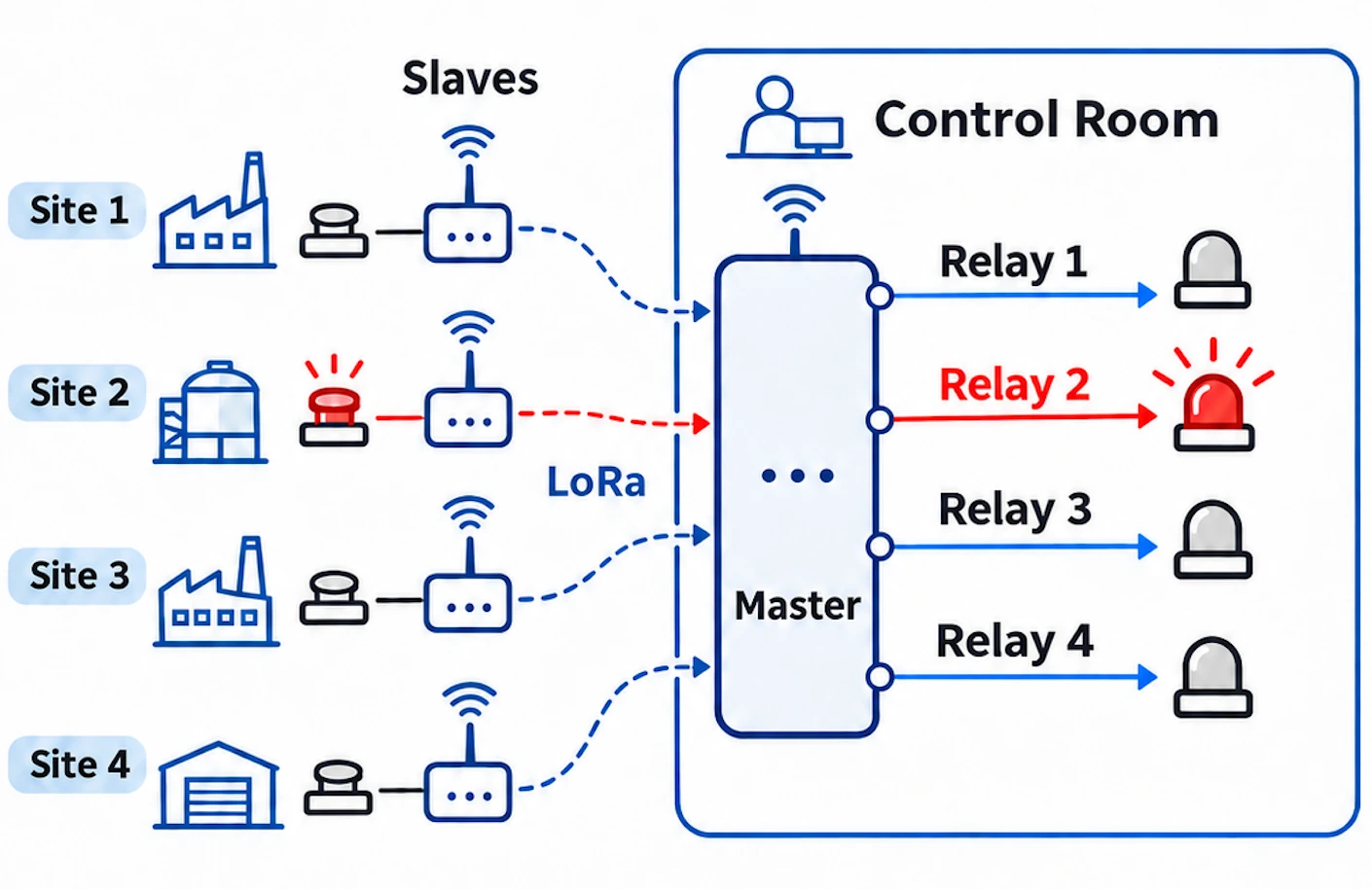
Install one slave in each area and connect the area's button to its digital input (DI). In the control room, assign the four slaves to separate master channels, DO1–DO4, and connect each relay output to its area's indicator.
Press Area 2's button: Slave 2 sends the contact state over LoRa, the master energizes DO2, and Area 2's indicator lights up. The other three slaves have their own outputs, so the panel shows which area raised the alarm.
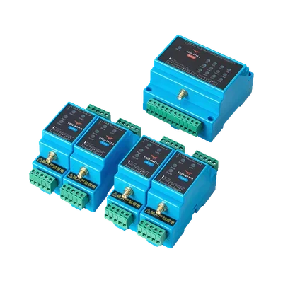
The Y402-41-L specification defines a 4DI/4DO master and up to four 1DI/1DO slaves. The mapping works in both directions; this example uses the slave-to-master direction. During normal communication, each output resets when its associated input opens.
For a common sounder, use external relay logic or a controller to combine the signals while preserving the four area indicators. The master has no additional built-in common-alarm output.
Why choose Y402-41-L for this layout?
Y402-41-L assigns each slave to a separate master output. That relationship is the reason for choosing it here: the output tells the control room which remote alarm point is active. Other models handle the signals differently.
| Model | Signal relationship | Fit for this design |
|---|---|---|
| Y402-41-L | Each of up to four single-channel slaves maps to one assigned master channel. | One master distinguishes four area slaves through DO1–DO4. |
| Y402-44-L | Corresponding slave inputs are aggregated: any slave's DI1 activates master DO1, and likewise for channels 2–4. | The output identifies the input channel, without identifying which slave activated it. |
| Y401-44-L | Two paired devices exchange four corresponding channels. | Four channels at one remote endpoint; it does not provide four independently located wireless slaves. |
| Y401-11-L | One independent channel between two paired devices. | A separate pair can carry each area-and-level signal, with more receiving modules at the control room. |
On Y402-44-L, DI1 on any slave activates the same master DO1. If every area's button uses DI1, the output cannot identify the area. The Y402-44-L operating logic also keeps that output active until DI1 on all slaves returns to open during normal communication.
You could reserve a different Y402-44-L input channel for each area, but that identifies areas through channel allocation. Y402-41-L provides an explicit slave-to-output assignment, which is the arrangement used throughout this guide.
Y401-44-L is a useful alternative if four level contacts in each area can be wired to one local module. Four point-to-point pairs could then carry four levels from four areas. Choose that layout when local wiring is practical; the examples below give each dispersed alarm point its own wireless module.
Add a separate system for each alarm level
Suppose each area now needs a routine notification and an urgent alarm. Each Y402-41-L slave has only one input. Connecting both buttons to it would lose the distinction between the two levels.
Give each level its own slave in each area. One master and four slaves carry routine notifications; a second master and four slaves carry urgent alarms. Label the two systems accordingly. An urgent input in Area 3 activates DO3 on the urgent-alarm master. The system label identifies the level, and the output channel identifies the area.


For four levels, use four systems, each serving the same four areas. Label them L1–L4 and define what those levels mean for the plant. The modules transfer contact states; the panel labels and external alarm logic assign their meanings.
Use the same area-and-level labels on buttons, modules, terminals and the panel. If alarms can occur together, define sounder priority, acknowledgement and reset behavior in the external panel logic.
How many modules do the two designs need?
Y401-11-L can carry each alarm signal over its own point-to-point pair. One module sits at the alarm point and the other at the control room. The difference becomes clear as the number of alarm points grows.
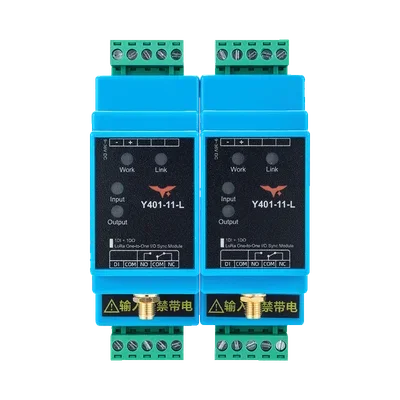
| Four-area configuration | Y401-11-L | Y402-41-L |
|---|---|---|
| One alarm level | 4 pairs: 4 field + 4 control-room modules | 1 system: 4 slaves + 1 master |
| Four alarm levels | 16 pairs: 16 field + 16 control-room modules | 4 systems: 16 slaves + 4 masters |
| Total modules at four levels | 32 | 20 |
Both four-level designs use sixteen field modules. At the control room, Y402-41-L needs four masters instead of sixteen Y401-11-L receiving modules: twenty modules in total, compared with thirty-two. There are still sixteen independent output circuits for the sixteen area-and-level indications.
Fewer control-room modules reduce DIN-rail space and module power connections. Compare module quotations, power supplies, antennas, enclosures and installation work to calculate the total cost. These counts assume direct radio links; relay extensions need extra modules.
Expand in groups of up to four areas
For each alarm level, assign Areas 1–4 to one master and Areas 5–8 to another. A fifth area starts a new group because each master serves at most four slaves. The last group can have fewer than four.
| Areas | Levels per area | Masters / systems | Slaves |
|---|---|---|---|
| 4 | 1 | 1 | 4 |
| 4 | 4 | 4 | 16 |
| 6 | 2 | 4 | 12 |
| 8 | 4 | 8 | 32 |
For this grouping, masters = alarm levels × area groups, with the area count divided by four and rounded up. Slaves = areas × alarm levels. Six areas with two levels therefore need four masters and twelve slaves.
These are device quantities. The basic package contains one master and one slave, so specify any additional slaves when ordering. Confirm pairing and group separation, then test all systems together, including simultaneous alarms and masters installed next to each other.
Extend the signal through two radio segments
If the direct link is too long or obstructed, first review antenna positions and the route. The Y402-41-L range specification lists up to 5 km in an open area for the standard version, with a 10 km option for selected configurations. Test the actual site; open-area range does not establish coverage through buildings or metal structures.

Where a powered intermediate station can communicate with both ends, link two wireless I/O systems: Slave 1 → Master 1 → Slave 2 → Master 2. Each system provides a LoRa segment, with a wired relay-to-input connection between them. This is an electrical handoff, not automatic radio repeating or mesh routing.

At the intermediate station, connect Master 1's assigned relay NO contact to Slave 2's DI, and that relay's COM to the slave's input COM. Use the dry contacts only; do not apply external voltage to DI. Power both modules locally.
- The originating button closes Slave 1's input.
- Master 1 receives that state and closes its assigned normally open relay contact.
- That dry-contact closure activates Slave 2's input at the intermediate station.
- Slave 2 sends the state over the second radio segment; Master 2 activates its assigned control-room output.
Keep a separate handoff for every signal you need to distinguish. Four independent outputs from Master 1 need four downstream slave inputs—four slaves—which can map to Master 2's four outputs. Combining them into one input would leave only a common alarm at the destination.
Choose an intermediate position that improves both radio paths, provide power and configure the groups for their intended links. Each stage adds processing and another link to test. Measure end-to-end response and interruption/recovery behavior; adding open-area range figures does not establish an installed distance or a guaranteed delay.
Check wiring, link loss and alarm reset
Follow the Y402 user manual for wiring, pairing and commissioning. The modules need 9–36 V DC. Inputs accept dry contacts or NPN open-collector signals, with no external voltage applied to DI. Relay contacts need an external load supply and protection suited to the lamps or sounder and the output ratings.
The master's Link 1–4 indicators show the corresponding links. Decide separately how a lost link should notify the operator; a link indicator does not itself provide an audible fault alarm.
After communication loss, the receiver retains the last relay state for approximately 80 seconds. If the link has not recovered, the relay de-energizes and NO–COM opens. In a relay chain, a retained output can also hold the next stage's input active.
If an alarm must remain displayed after the button is released or a link fails, provide alarm memory and manual reset in the external logic. Input following alone does not store an alarm. See wireless I/O link loss and recovery for the difference between a current input and a retained output.
- Check every alarm point: operate each button and confirm the exact area and level on the panel.
- Trigger alarms together: check simultaneous indications, sounder priority, acknowledgement and reset.
- Interrupt each stage: test loss of radio communication and local power at the installed antenna positions.
- Restore each link: check the panel response with inputs both active and inactive.
The Y402-41-L specification excludes guaranteed timing and use as the sole emergency-stop or personnel-safety path. Any required safety function needs its own appropriate design.
Before connecting the alarm loads, verify the full path from each button to its assigned panel output, including any relay stages. A separate, consistently labelled path for every area and level is what makes the notification useful to the operator.