
Periodic manual inspection
Scheduled walkthroughs do not provide continuous gas, smoke or water-level readings.
TUNNEL & UTILITY CORRIDOR MONITORING
Gas, Water-Level and Equipment Status Monitoring with Alert Linkage
For tunnels, utility corridors, municipal and industrial pipelines, connect gas, water-level, temperature/humidity, equipment-status and manual alarm signals, then configure alerts, local linkage and operating records by project.
On site
Long routes and distributed equipment require continuous sensing, coordinated response and complete event records.
Scheduled walkthroughs do not provide continuous gas, smoke or water-level readings.
Fans, pumps, lighting and signage may be installed across long routes, increasing the time required for manual operation.
Fire, smoke, gas or flooding may require several equipment groups to operate under the same response rule.
Without trend data, safety decisions rely on manual observations instead of measured change over time.
System workflow
Separate environmental measurement, auxiliary signaling and approved local protection.
Compatible instruments or local controllers provide environmental readings and contact signals.
Y403-11-L nodes forward contact states: any input activates all linked outputs until every input is released.
Matched local control and protection systems determine the permitted fan, pump, lighting or alarm response.
A suitable gateway and application collect available status, alerts and event records.
Y403-11-L is for auxiliary non-safety control and signaling. Scenario-specific or independent equipment groups require appropriate external control; certified safety functions remain with the approved local system.
Monitoring and control
Each capability links a system function to an operational result.
CO, CH4, H2S, O2, temperature, humidity, and water level are collected continuously so your team sees tunnel conditions as they change.
Y403-11-L auto relay logic lets one dry-contact trigger energize outputs across peer nodes for coordinated response.
I/O modules connect equipment control points and return status so operators can start fans, pumps, and lights without entering the hazard zone.
Critical zones can add camera-based smoke and fire recognition for visual confirmation before escalation.
Managers receive data, alarms, records, and trend curves from a phone when they are away from the control room.
Large-screen visualization lets operations staff scan alarm state, current readings, and trend history from one place.
Monitoring and control
Automated linkage can connect a detected condition to predefined equipment actions while retaining an event record.
| Monitoring only | Configured auxiliary linkage |
|---|---|
| Sensor detects gas, alarm appears, operator notices, calls a crew, then someone enters the tunnel to start equipment. | Sensor contact closes, Y403-11-L DI triggers, interlocking propagates through the mesh, and DO outputs energize across the line. |
| Fans, pumps, lights, and signs behave like independent islands that require manual coordination. | Within a standard Y403-11-L network, any active input energizes all linked outputs. Independent response groups require appropriate external control or separate project-defined systems. |
| Response time depends on staffing, phone calls, distance, and access conditions. | A configured local linkage can initiate equipment actions without waiting for manual coordination. |
| Network outages create alarm gaps and make later reporting harder. | Self-healing mesh and gateway buffering help preserve communication and historical records. |
| After the incident, teams reconstruct events from fragmented logs. | Detection, trigger, equipment response, operator action, and resolution are kept in one event timeline. |
Application examples
Highway tunnels, utility corridors, metro passages and mine tunnels require monitoring points and response rules suited to their equipment and operating conditions.
CO or smoke condition triggers ventilation, lighting, signage, and portal response.
CH4, H2S, water level, and heat alerts activate fans, pumps, and maintenance notifications.
Temperature, humidity, and emergency lighting status feed the control room for rapid response.
Water-level escalation can start primary and backup pumps before flooding spreads.
Deployment planning
Map tunnel length, equipment rooms, pump stations, lighting panels and monitoring points before selecting the communication and response paths.
Map tunnel layout, monitoring points, gateway positions, and equipment control wiring.
Deploy sensors, Y301 I/O modules at control points, and Y403 LoRa mesh nodes along the tunnel.
Validate mesh paths, interlocking rules, Modbus TCP equipment points, alert thresholds, and cloud dashboards.
Begin continuous monitoring, automated linkage, mobile alerts, trend analysis, and compliance reporting.
Map tunnel length, equipment rooms, pump stations, lighting panels, monitoring points and access points.
Place monitoring nodes, I/O modules, mesh controllers and gateways according to the route, equipment rooms and uplink plan, then connect the configured points to YenGear IoT Cloud.
The monitoring center can receive line-wide status, alerts and event records, while local linkage rules can connect water-level conditions to configured pump actions.
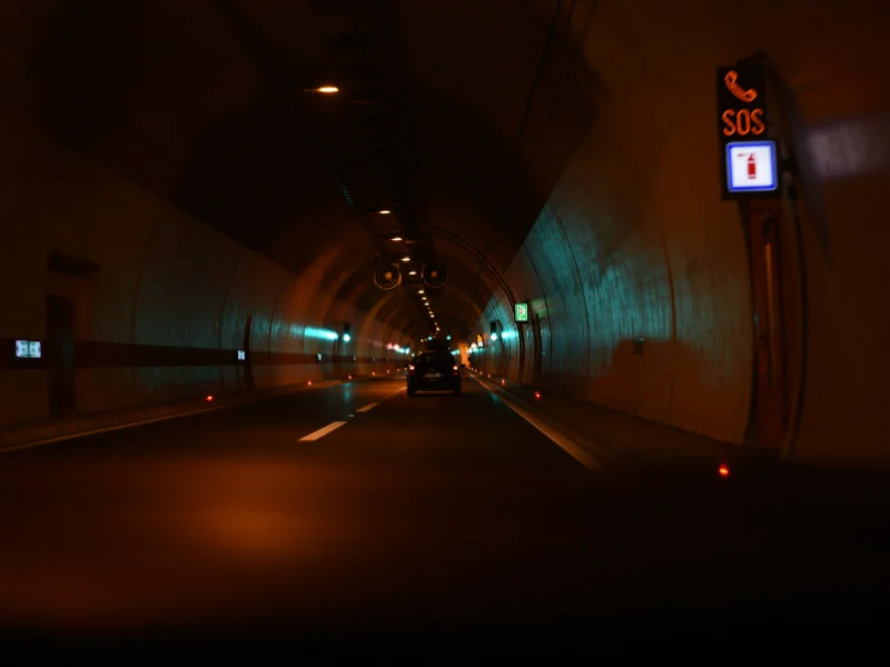
Deployment planning
The deployment design covers hardware ratings, field networking, uplink paths and event records for underground conditions.
Wide DC input, industrial mounting, and product-rated temperature and humidity ranges support harsh tunnel environments.
Y403-11-L LoRa mesh nodes can relay and reroute signals across long corridors without relying on one central controller.
Ethernet, LoRa mesh, gateway uplink, and optional 4G backup reduce dependence on one communication path.
Detection, linkage trigger, equipment response, operator action, and resolution data are retained for review and reporting.
System components
These products provide the I/O and LoRa linkage functions used in the architecture.
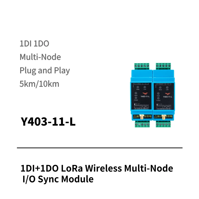
Auxiliary contact linkage
Y403-11-L builds a local automatic-relay network for emergency response.
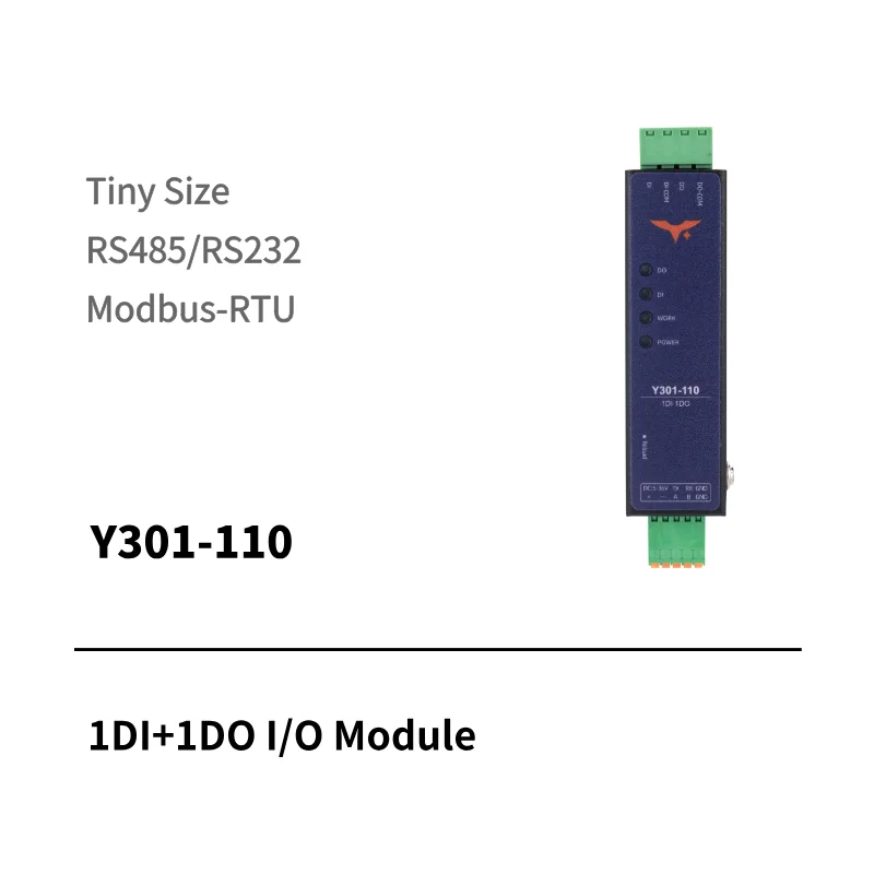
Field connection
Y301-110 provides one digital input and one relay output for local equipment control.
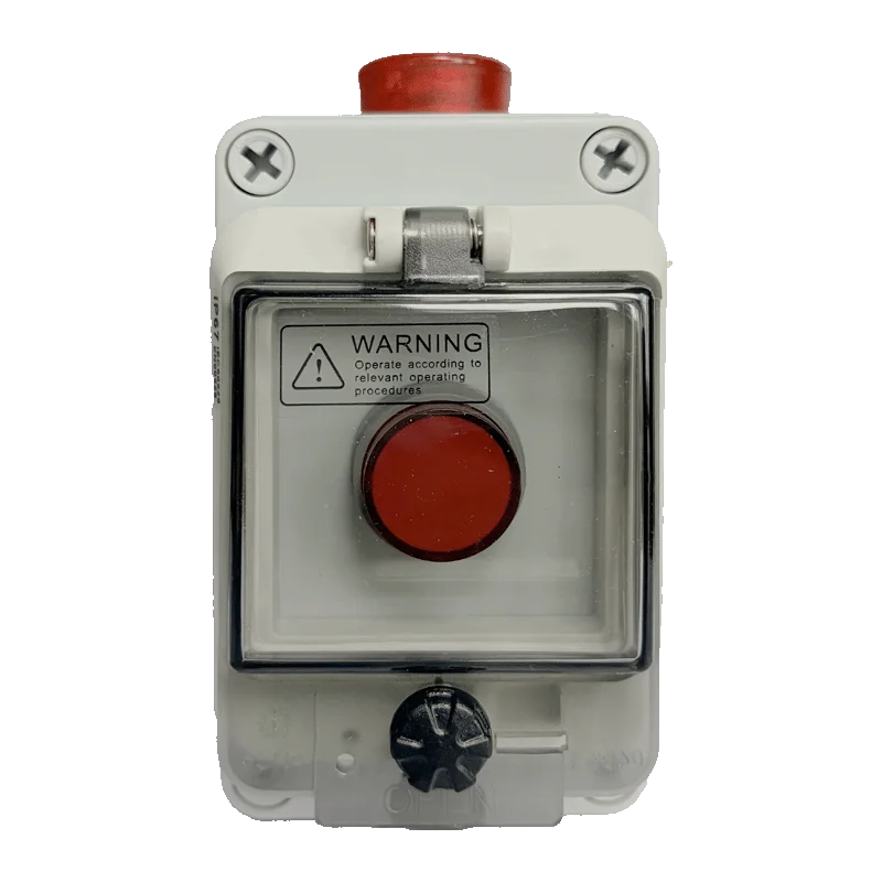
Staff-operated warning
Multi-point audible-visual warning triggered by staff through the built-in latching button. Automatic sensor alarm triggering is not a standard input.
Answers about connectivity, integration, mesh behavior, configuration and pricing.
In-tunnel communication can use LoRa mesh between Y403-11-L nodes, while gateways near suitable access points may uplink through Ethernet or a cellular backup. The positions, path redundancy and recovery behavior require a site plan and test.
Integration can be evaluated through Modbus TCP/RTU, OPC-UA, an API or a project-specific gateway. Confirm the point list, write permissions, network boundary, response requirements and responsibility for each control action.
LoRa is intended for long-range, lower-bandwidth field signaling, while Wi-Fi depends more heavily on local access-point coverage and network design. Mesh relaying or alternate paths may be used, but topology and recovery must be verified for the tunnel.
Scenario-specific rules require a suitable external controller and the approved local control design. Standard Y403-11-L nodes share an any-input / all-output contact-linkage behavior.
A compatible gateway may buffer readings and backfill history after connectivity recovers. Whether local interlocking continues depends on the controller and project configuration, so the interrupted, restored and manual-override states must be tested.
Tunnel length, monitoring point count, sensor types, controller count, gateway configuration, integration scope, and cloud or on-premise deployment model.
Tunnel safety assessment
Tell us the tunnel length, monitoring points, equipment groups and existing SCADA or PLC.