
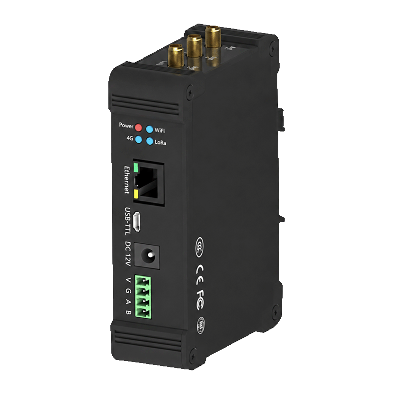
Indoor gateway
Y501-L
Forward LoRaWAN packets to an external Network Server. Local NS/AS is a software option.
Ethernet, Wi-Fi, RS485; optional 4G
LoRaWAN products
Bring RS232, RS485 and field I/O into your LoRaWAN network. Choose the gateway, end device and server configuration for your equipment.
Gateway-based networking with a local or external Network Server.
Choose your hardware
Choose a gateway for the network, then a serial or I/O end device for the equipment. Already have a LoRaWAN network? Start with the field devices.
Two indoor gateways. Choose the software around your server and application.
Indoor gateway
Forward LoRaWAN packets to an external Network Server. Local NS/AS is a software option.
Ethernet, Wi-Fi, RS485; optional 4G
Indoor edge gateway
Decode payloads locally and map data to Modbus registers with the local NS/AS software option.
Ethernet, Wi-Fi, RS485; optional 4G
Serial data or direct signals. Match the end device to the equipment interface.
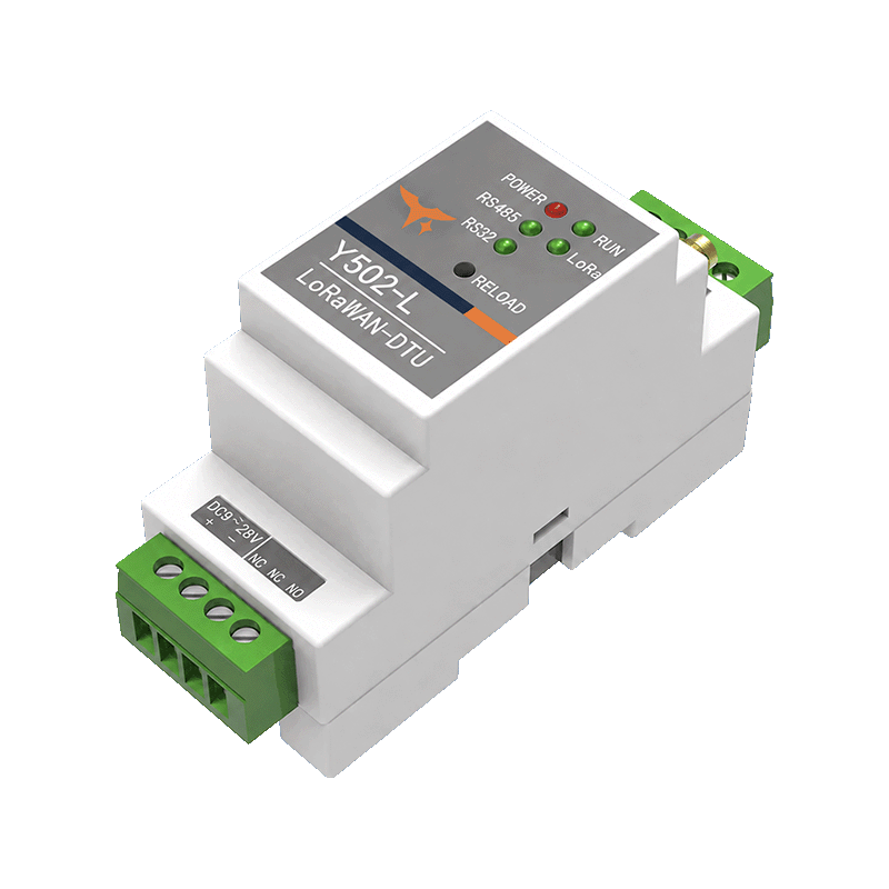
Serial DTU end device
Poll serial equipment or carry serial frames over LoRaWAN. No onboard I/O channels.
1 isolated RS485 + 1 isolated RS232

I/O RTU end device
Collect field contacts and analog signals, with voltage-output commands via LoRaWAN.
1 isolated RS485, 2 DI, 2 voltage DO, 1 AV + 1 AI
Gateway images show the shared enclosure design. Antennas, connectors and hardware options depend on the ordered configuration.
From equipment to application
The end device collects your data. The gateway forwards radio packets. The Network Server manages device sessions, and the application interprets the payload.


The optional local NS/AS runs the Network Server and Application Server on the gateway. Those software services remain separate from the gateway’s radio-forwarding role.
Application integration
Use an existing Network Server, or specify the local NS/AS software option. Your server interface determines the configuration.
Equipment connections
Typical configurations to discuss for your project. Equipment protocols, payloads and control behavior still need to be matched.
Y502-L polls Modbus RTU equipment or carries custom RS232/RS485 frames. Use it when the measurement already exists in a serial device.
See the serial DTUY503-222-L provides 2 DI, one 0–10 V input and one 4–20 mA input. Its two outputs switch supply voltage, not dry relay contacts.
See the I/O RTUUse the Network Server’s application delivery, or Y511-L local-service interfaces and Modbus mapping. Check data age before using mapped values.
Compare integration pathsBefore you specify
Match the regional plan, data traffic and equipment behavior before choosing the final configuration.
Node, gateway and Network Server must use a matching plan and channel group. Specify the installation country and AS923 sub-plan where applicable.
Availability depends on the ordered variant. A listed frequency plan is not a certification or deployment approval.
Both gateways offer 8 RX / 1 TX or 16 RX / 2 TX configurations. Channel count is not a node-capacity rating.
Reporting interval, payload size, airtime, interference and downlink traffic determine usable capacity.
Class A receives downlinks after an uplink. Class C keeps reception available more often. Neither guarantees fixed command latency; regional limits and network scheduling still apply.
All four models use 9–28 VDC power. Match serial settings and signal types; size the supply for the device and connected loads.
Y503-222-L has fixed AV/AI terminals and no analog output. Its DO voltage follows the supply.
Confirm output ratings, startup and communication-loss behavior, and independent local protection. Test the complete command and equipment-response path before unattended operation.
Technical resources
Check electrical ratings in the specification, then use the manual for wiring, activation and configuration.
Questions about LoRaWAN architecture, interfaces and product selection.
Looking for direct private LoRa I/O?LoRaWAN products use a LoRaWAN network with a gateway and Network Server. Y401, Y402 and Y403 Wireless I/O products use a private LoRa link for direct signal transfer. Choose the architecture before selecting the hardware.
Y501-L normally forwards radio packets to an external Network Server. Local Network Server / Application Server (NS/AS) software is available as an option for installations that need these services on the gateway.
With local NS/AS enabled, Y511-L supports HTTP uplink, acknowledgement and gateway-status delivery, and a TCP client connection to an application server. Match message fields, payload encoding, authentication and TCP framing. Downlink control needs a supported interface and application adaptation; HTTP delivery is not a bidirectional control API.
LoRaWAN does not guarantee a fixed response time. Class A end devices receive downlinks in windows after an uplink. Class C provides more receive opportunities, but radio conditions, regional limits, gateway scheduling and server processing still affect delivery. Validate the application timing and use appropriate independent local protection.
No. Y503-222-L has voltage outputs that follow the RTU supply voltage. Check load voltage, current, wiring and protection against the specification before connecting equipment. Its analog inputs are one fixed 0–10 V AV channel and one fixed 4–20 mA AI channel; there is no analog output.
Provide the installation country, regional plan and channel group, including the AS923 sub-plan where applicable. Match the node, gateway and Network Server configuration. Frequency availability varies by model, so confirm the exact variant before ordering.
Product selection
Tell us your installation country and the equipment or signals. We’ll help choose the end device, gateway and server configuration. No model number needed.
If known, add your node count, reporting interval and existing server. Please leave device keys and passwords out of your message.