
01 / Digital I/O
Sequence equipment operation
Read start, stop and equipment status contacts. Combine permissive conditions and timers to control an external contactor or alarm circuit.
Inputs → program conditions and timing → output circuit
Y305 PLC I/O Modules
Run your control program where the signals and equipment connect. Choose digital I/O, with 0–10 V analog I/O on selected models.
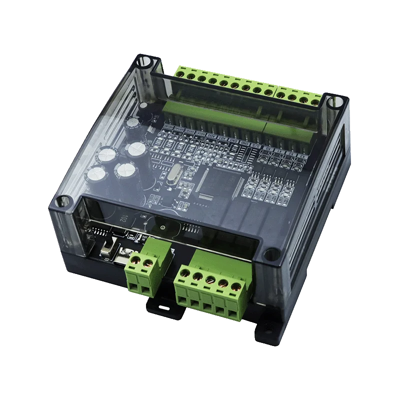
Local control
Read field signals, evaluate your logic and drive outputs from a program running on the Y305. Combine conditions, timers, sequences and interlocks for the task.
Connect switches and compatible sensors to the fitted digital and analog inputs.
Process states and timing in local PLC logic, using an FX3U-style device and instruction model.
Switch suitable load circuits through relay or NPN outputs. Analog-equipped models also provide a 0–10 V output.
Y305 uses GX Works2. Confirm the software version, project setup and programming interface for the supplied hardware and firmware. Test the program before connecting equipment.
Application examples
Define the conditions and output actions in your program, then test them against the equipment and its electrical limits.
01 / Digital I/O
Read start, stop and equipment status contacts. Combine permissive conditions and timers to control an external contactor or alarm circuit.
Inputs → program conditions and timing → output circuit
02 / Digital + analog I/O
A model ending in 21 reads a 0–10 V level signal. Program the operating conditions and control a suitably rated external pump contactor. The 0–10 V output can send a command to a compatible receiver.
Level + status → program logic → contactor / analog command
These are design examples, not preloaded programs or safety functions. Validate wiring, interlocks, startup and recovery on the intended equipment.
Choose the control role
Start with where the application logic will run, then compare signals and electrical limits.
Run a user PLC program on the module to combine field inputs, timing and output control. Add RS485 when communication is needed.
Compare Y305 modelsConnect field I/O to an existing Modbus host. Selected Y301 models also support local rules, including relay and analog threshold rules.
Explore Serial I/OY305 model selection
Select digital channel count, then choose whether your application needs 0–10 V analog I/O.
4 DI · 4 DO
No analog I/O
Specification4 DI · 4 DO
2 AI + 1 AO · 0–10 V
Specification8 DI · 8 DO
No analog I/O
Specification8 DI · 8 DO
2 AI + 1 AO · 0–10 V
Specification14 DI · 14 DO
No analog I/O
Specification14 DI · 14 DO
2 AI + 1 AO · 0–10 V
Specification18 DI · 18 DO
No analog I/O
Specification18 DI · 18 DO
2 AI + 1 AO · 0–10 V
SpecificationThe code positions represent DI / DO / AI / AO. E = 14 and J = 18. Relay outputs and RTC are standard; NPN transistor outputs and RS485 are specified separately. Confirm availability and electrical limits for the ordered hardware.
Channel count is the starting point. Match the ordered hardware to the complete circuit and control task.
Relay contacts are the default; NPN transistor outputs are an option for DC loads. Check voltage, load type, inrush, common-terminal and protection requirements.
Models ending in 21 provide 2 AI and 1 AO at 0–10 V. Select the required RS485 port configuration separately.
RTC is standard. Confirm clock backup and recovery; specify any high-speed counting or pulse requirements for the hardware.
Review wiring, the first program and registers before integrating the module.
Questions about programming, signals and choosing a Y305 module.
Y305 runs a user PLC program for local control. Y301 primarily connects field I/O to a serial host; selected Y301 models also support local rules. Choose according to the control logic, signals and interface your application needs.
Y305 uses an FX3U-style device and instruction model with GX Works2. Confirm the software version, project settings, programming interface and transfer procedure for the delivered hardware and firmware.
Y305-4421, 8821, EE21 and JJ21 provide two 0–10 V inputs and one 0–10 V output. Models ending in 00 have no analog I/O. Do not connect a 4–20 mA loop directly to the voltage inputs.
Relay outputs switch a contact circuit and are the default. Optional NPN transistor outputs sink DC current. Confirm load voltage, current, inrush, common-terminal ratings and protection for the supplied hardware before wiring.
A Y305 can run its local PLC program without an external controller. RS485 is an ordering option for communication with other devices; specify the required ports and verify the configuration.
No. Do not use Y305 as a safety PLC or the sole protective control. Provide independent safety functions where required.
Share the equipment, input signals, output loads, channel count and any communication requirements. We can help you identify a suitable configuration.