A wireless I/O module rarely drops its outputs the moment the radio goes quiet. Many keep the last state until a timeout expires, and some switch an output back on when communication returns. Normal signal transfer tells you little about either behavior.
Before comparing range, channel count or response speed, answer three questions: what the output does during the outage, whether the feedback still describes the equipment, and what allows operation to resume.
A green light raises a different question
An engineer evaluating wireless I/O for temporary traffic lights raised a concern: if a connection failed while one signal was green, could that signal stay green while the controller allowed the other direction to proceed? The engineer also wanted to know whether restoring communication could turn a relay back on without a new command.
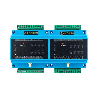
The Y401-44-L considered in this inquiry provides four digital inputs and four relay outputs per unit, with corresponding channels linked across a point-to-point LoRa connection. Reproducing a contact state does not provide the conflict prevention and restart supervision needed for traffic signals. The same interruption and recovery questions arise when a remote relay controls a pump, fan or valve.
Does losing the link turn the output off?
Usually not straight away. A receiver cannot read an OFF command into silence, so what it does next depends on the fault rule built into it.
For the Y401-44-L, the published rule is a hold followed by a reset. After communication is lost, the receiver keeps its last relay states for about 80 seconds. If the link has not recovered by then, the relays de-energize and the normally open (NO–COM) contacts open. In the traffic-light scenario, a lamp wired through NO–COM could therefore stay green for more than a minute after the radio link fails.
| Behavior | What it means | What to confirm |
|---|---|---|
| Hold the last state | The output retains its previous value during the specified fault condition. | Whether this is indefinite, time-limited or overridden by another fault. |
| Apply a fault state | The output changes to a defined value after the device declares a communication fault. | The detection rule, timeout and action for each output. |
| Require periodic refresh | An output remains enabled only while valid refresh commands arrive within an allowed interval. | Which messages refresh the timer, and what happens when they stop. |
These behaviors can be combined. The Y401-44-L holds the last state first, then applies a fault state at the timeout. Another module may use only one of them, or let you configure each output differently.
Link interruption, fault detection and output action are separate events
A timeout may be counted from the last valid command, an unanswered poll or another protocol event. The physical interruption can happen between those events. Retries, polling intervals and output processing can also affect when an action is observed. A Link LED may use a different indication rule, so its change is not a substitute for measuring the output.
That is why a stated hold time, such as the Y401-44-L's 80 seconds, is approximate. Measure the delay between interrupting the link and the contact change on your own bench. Other products count differently: Banner's DX80 Performance manual, section 7.2.5, for example, declares a timeout after a number of unanswered polling cycles.
What does a feedback signal actually prove?
A command says what the controller requested. A module status says what the module reports. Equipment feedback says what a separate measurement detects. Those signals answer different questions, even when all three appear as a single ON/OFF bit on a screen.

In the traffic-light example, a returned module-output bit does not by itself prove that a lamp is illuminated. A broken lamp, external power loss or a wiring fault can separate the commanded state from the physical result. A separate sensor can provide different evidence, but its coverage and failure behavior also need checking.
A correct old value can still be unusable
Suppose the controller last received ON before the return path failed. The display may still show ON even though it no longer knows the remote equipment's present state. The value was not necessarily wrong when received; it has become stale.
Where the system supports them, use a last-update time, validity indication or timeout status alongside the value. Confirm what actually updates that indication: a newly sampled remote input, a valid radio exchange or just a local read of a cached register. If the module exposes only a retained bit, the controller needs another supported means to judge its freshness.
An invalid or unknown state is also different from a confirmed OFF state. In the traffic-light scenario, losing confirmation of the opposing light's state cannot be treated as proof that the opposing traffic has stopped.
Can the output turn on again when the link returns?
Yes, depending on the recovery policy. With automatic input-to-output following, the transmitter may send its current input again after communication recovers. If that input is still ON, a receiver may energize the corresponding output without anyone operating the original switch again.
A different design can keep a faulted output inhibited until a defined restart condition is met, such as a new enable command, a deliberate input transition or an operator reset. A hardware watchdog does not imply any of these.

The Y401-44-L documentation describes input following and the timeout reset, but no separate restart condition. Because each output follows its remote input, test whether an output re-energizes when the link returns while that input is still ON. If the application must not restart on its own, the inhibit has to come from the controller or the equipment.
Power-up behavior does not answer the recovery question
A module that starts with its outputs OFF may still resume following an active input after reconnection. Ask separately about receiver startup, transmitter startup, a controller restart and a radio-only interruption while both modules remain powered.
Also ask whether the receiver uses the latest state, processes queued transitions or accepts commands left over from before the interruption. A faster radio does not, by itself, define any of these policies or add a restart interlock.
What should you confirm before choosing a module?
Write down the required behavior before comparing products. Ask for answers tied to the exact hardware, firmware, operating mode and configuration rather than a general statement that a device has “fail-safe” or “reliable communication.”
| Area | What to confirm |
|---|---|
| Loss detection | What event starts or resets the timeout, and which delays are included? |
| Output action | What happens to each output, and what timing bounds apply under the stated conditions? |
| Feedback | Does it report a command, module state or measured equipment state? How is stale data identified? |
| One-way failure | What happens if commands arrive but feedback or acknowledgements do not, or the reverse? |
| Recovery | If the input remains ON, can the output reactivate? Is a separate restart condition supported? |
| Power and startup | What happens when either end restarts or loses power independently? |
| State changes | Are missed or queued transitions discarded, replayed or replaced by a current-state update? |
| Verification | Which test report, manual section and configuration demonstrate the specified behavior? |
Verify the sequence on a controlled bench
Use isolated test indicators or a simulator before connecting operational equipment. Record the input, received status, output and feedback together, with enough timing resolution to check the requirement. For each test, retain the configuration and observed sequence rather than recording only “passed.”
- Interrupt an active link: keep the input ON and record what each end reports and when the output changes.
- Restore the link with the input unchanged: observe whether the output resumes automatically or remains inhibited.
- Change the input while disconnected: check whether recovery applies the current state or produces intermediate transitions.
- Restart each end separately: compare transmitter, receiver and controller restarts with a radio-only interruption.
- Check feedback loss: where the test setup permits, interrupt the return path and verify that retained data is not presented as a fresh confirmation.
An interruption shorter than the timeout and one long enough to trigger the fault can produce different results; check both. For the Y401-44-L, that means outages well under and well over 80 seconds. A bench test establishes observed behavior for that setup. It does not establish every field condition or qualify the complete installation for a safety-related application.
Where does communication end and system protection begin?
Return to the engineer's traffic lights. One question is whether the receiver stops holding a green request; with the Y401-44-L it does, after about 80 seconds. Another is what prevents the opposing direction from being released while that state is unknown. A third is how both ends return to a coordinated operating state after a fault. A relay timeout answers only the first.
Queensland's MRTS264 portable traffic-signal specification, section 8.1.1 treats communication loss and conflicting green signals as critical system faults. It is a useful example of the scope of dedicated traffic-signal protection, not evidence that a particular wireless I/O module is approved for traffic control or that the same requirements apply in another jurisdiction.
Before connecting the load, confirm the output state during a fault, how stale feedback is identified, and what permits a restart.
Related reading
If the network terminology is unclear, read What Is LoRaWAN? for the distinction between the LoRa radio layer and the LoRaWAN network protocol. Neither a radio name nor a network protocol label specifies a finished product's output fault state or restart policy.