
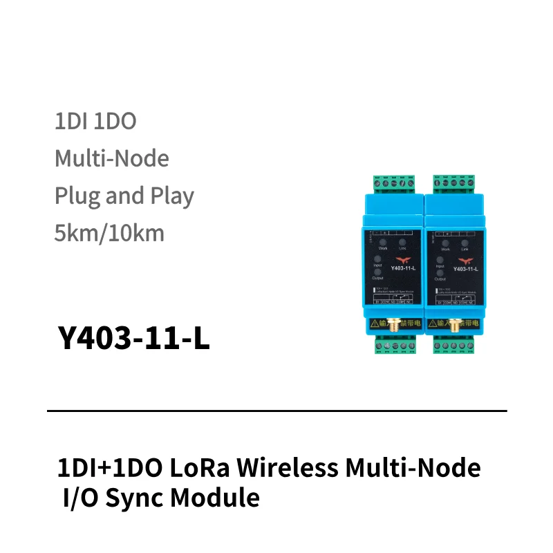
Equipment rooms can be scattered across a site while staff work in one monitoring room. When adding long control cables is difficult, a LoRa wireless I/O link can carry a door-contact signal to a relay beside the monitoring-room alarm.
This application example uses Y403-11-L modules to provide one shared alarm for several doors. Each door can trigger on opening or closing, provided its contact closes in the required alarm state.
Do you need a shared alarm or a door number?
One shared alarm
Y403-11-L
Any door input activates the linked outputs. Connect the monitoring-room relay to a common alarm.
Staff know a door has triggered, but the shared output does not identify which door.
See the shared-alarm layoutIdentify each door
Y402-41-L
Each door maps to a separate master output. Use labelled indicators or individual alarm-panel inputs.
Up to four door points per system. Deploy multiple systems for more doors.
See the channel mappingHow do several doors activate one monitoring-room alarm?
Install a Y403-11-L at each door location and another in the monitoring room. Connect each compatible door contact between its local module's DI and COM. Connect the monitoring-room relay to the alarm equipment. Each module needs a suitable 9–36 VDC supply.
Y403 uses multi-node linkage: any closed input activates every linked node's relay output, including its own. In this example, only the monitoring-room output is connected to alarm equipment; the door-node outputs are unused. The monitoring-room DI is left open. These are linked nodes, not a master/slave arrangement.
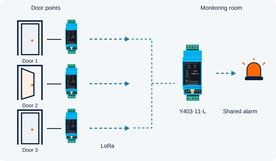
- Door contact closesThe selected door state connects DI to COM.
- LoRa carries the stateThe linked Y403 nodes activate their outputs.
- Monitoring-room alarm respondsThe relay switches the connected alarm circuit.
What if staff need to know which door triggered?
Use Y402-41-L when each door needs a separate indication in the monitoring room. One 4DI/4DO master serves up to four assigned 1DI/1DO slaves. A door contact closes its slave DI, and the corresponding master output DO1, DO2, DO3 or DO4 activates.
| Door point | Monitoring-room output | Separate indication |
|---|---|---|
| Door 1 → assigned slave DI | Master DO1 | Door 1 indicator / alarm input |
| Door 2 → assigned slave DI | Master DO2 | Door 2 indicator / alarm input |
| Door 3 → assigned slave DI | Master DO3 | Door 3 indicator / alarm input |
| Door 4 → assigned slave DI | Master DO4 | Door 4 indicator / alarm input |
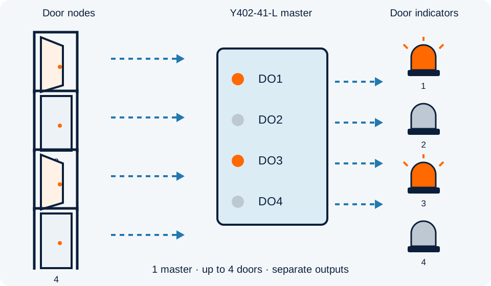
Connect those outputs to separately labelled indicators or distinct alarm-panel inputs. Door 1 then activates its assigned indication, while Door 2 activates another; simultaneous alarms remain on their respective channels. Combining all outputs into one unlabelled sounder would lose that identification.
One system supports at most four trigger points: four doors in this example. For more doors, deploy multiple separately configured systems. For six doors, for example, use two masters and six door slaves, grouped as four plus two, with each monitoring-room channel labelled to its door. Confirm pairing and radio coexistence during commissioning.
Y403 remains the shared-alarm option; Y402-41-L provides separate door channels. Neither a labelled relay channel nor its indicator is an event log or an automatic manual-reset function.
Can the alarm trigger when a door opens or when it closes?
Yes, by choosing or arranging the contact so that the required door state closes DI to COM. Y403 responds to the electrical input; it does not determine whether a door is physically open or closed.
| Required alarm | Contact connected to DI–COM | Normal condition |
|---|---|---|
| Door-open alarm | Closes when the door opens | Open circuit when the door is closed |
| Door-closed alarm | Closes when the door closes | Open circuit when the door is open |
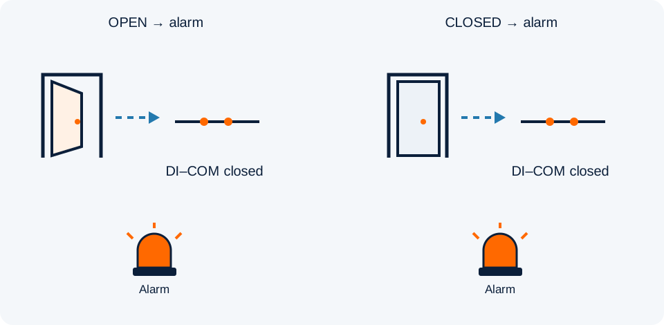
Check the sensor manufacturer's definition of NO and NC, then verify continuity with the door in both positions. Do not assume that every magnetic contact behaves the same way. A contact with the opposite behavior needs a compatible alternative or a suitable interface to convert the signal.
What happens when more than one door triggers?
With the link operating normally, the outputs follow the combined input state. Opening one input does not clear the shared alarm while another input remains closed.
| Door-node inputs | Monitoring-room relay |
|---|---|
| All inputs open | De-energized |
| Any one input closed | Energized |
| Several inputs closed | Remains energized |
| One input clears, another remains closed | Remains energized |
| All inputs return to open | De-energizes |
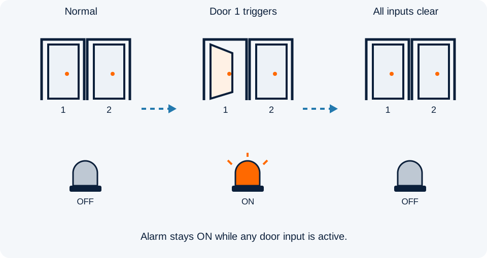
This is state-following control. If an alarm must remain active until an operator acknowledges it, provide that latching function in the alarm equipment or a separate control circuit. Silencing a sounder is also separate from clearing the Y403 input state.
How does the relay connect to the alarm equipment?
If the existing alarm panel accepts a dry-contact alarm input, connect the Y403 relay common and the appropriate NO or NC contact according to that panel's instructions. If switching a lamp or sounder directly, use an external load supply: the Y403 relay contact does not supply voltage.
Check voltage, operating current, startup current and load type against the relay specification. Use an appropriately rated interposing relay or contactor where required. DI accepts only a passive dry contact or compatible NPN open-collector signal; do not apply an external voltage to DI.
What should be checked before relying on the indication?
- Door behavior: test both physical positions at every door, including simultaneous triggers and the final return to normal.
- Radio path: test with equipment-room doors closed and antennas in their final positions. Walls, metal cabinets and antenna placement affect coverage.
- Power and link loss: confirm and test the required output behavior after a node loses power or communication. Do not treat silence as proof that every door is normal.
- Alarm operation: verify the connected alarm's polarity, sound/light response, silence function and reset behavior.
Y403 supports automatic signal relaying between nodes, but extra nodes do not guarantee coverage through every obstruction. Confirm the radio variant, permitted local frequency, power arrangements and actual communication path for the site.
Use this arrangement for auxiliary door-state notification. Door locking, emergency release and required life-safety functions remain part of the separately approved system.
Plan your door-alarm link
Start with the number of doors, the alarm state at each door, distance and obstructions, and whether one shared indication is sufficient. These details establish whether Y403 fits before wiring or purchasing equipment.