
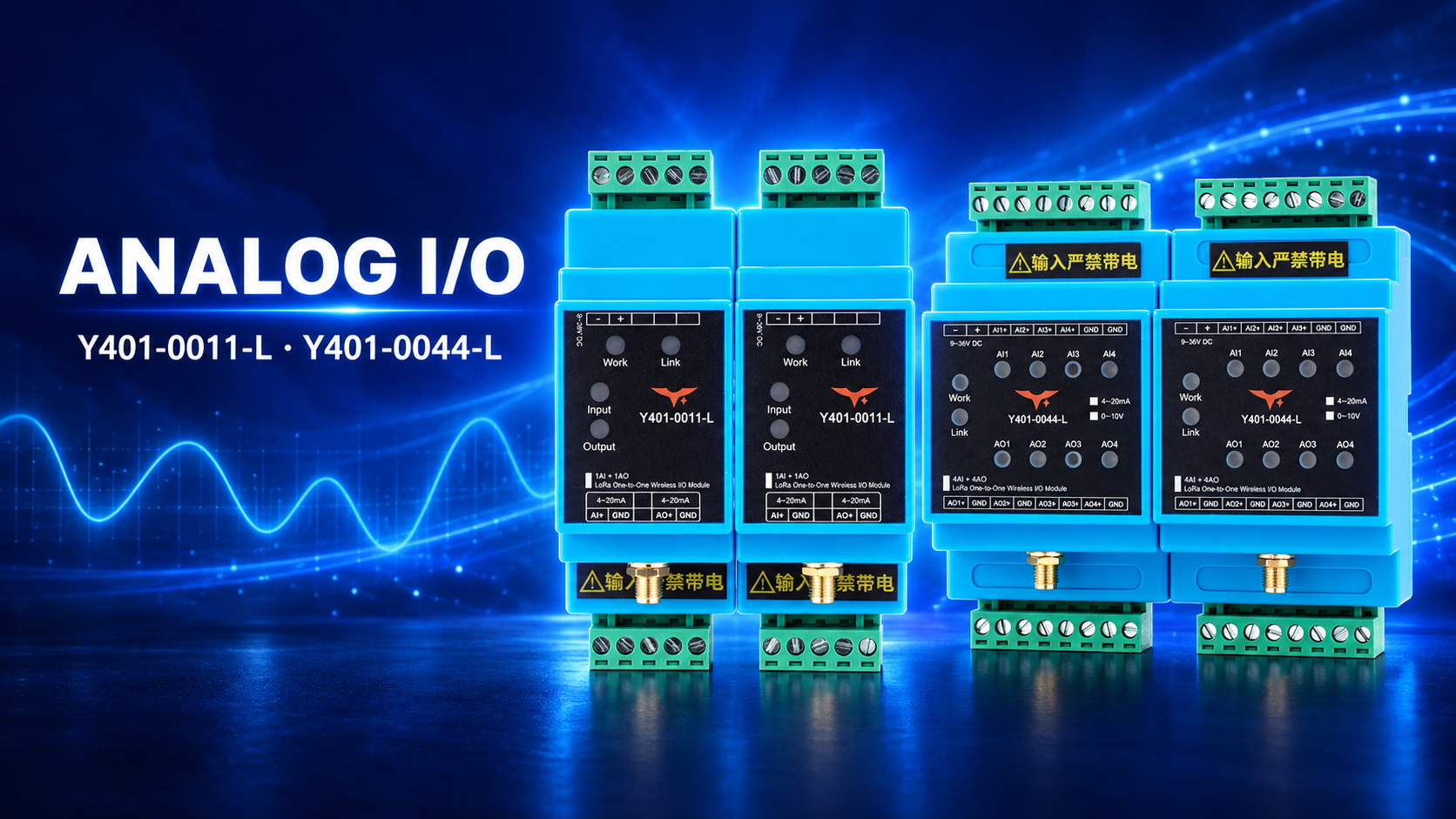
YenGear is introducing Y401-0011-L and Y401-0044-L for point-to-point wireless analog signal extension. They carry a field instrument's input signal over LoRa and reproduce it at the corresponding output on the other module, so a compatible indicator or PLC can receive the measurement without a long signal cable between the two locations.
These additions serve a different task from Y401-11-L and Y401-44-L. The digital models transfer contact states to relay outputs; the new analog models transfer continuous measurement signals. Choose by the electrical signal you need to carry, then by the number of channels.
One analog channel or four
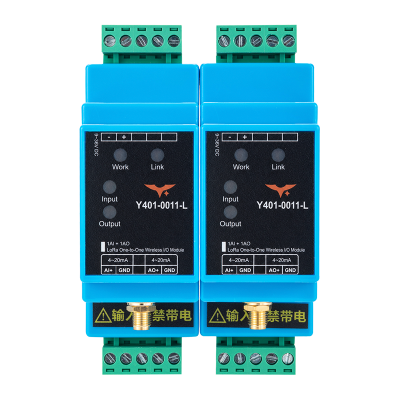
Y401-0011-L
Each module provides 1 AI and 1 AO for 4–20 mA. Two factory-paired modules form a link, with analog transfer available in both directions over a half-duplex wireless connection.
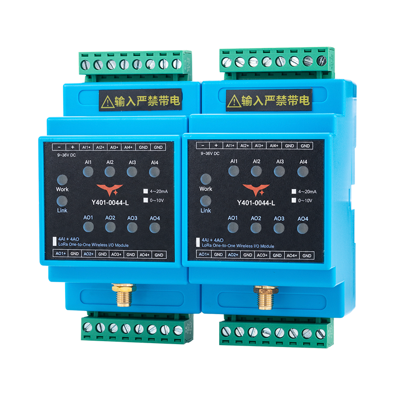
Y401-0044-L
Each module provides 4 AI and 4 AO, with 4–20 mA or 0–10 V options. A pair maps each input to the matching remote output. Specify the signal option when ordering; confirm selection method and any mixed-channel requirement.

How do they compare with Y401-11-L and Y401-44-L?
A float switch that changes contact state calls for digital I/O. A level transmitter that varies its current with tank level calls for analog I/O. More channels do not change this distinction.
| Model | I/O per module | Signal task |
|---|---|---|
| Y401-11-L | 1 DI + 1 DO | Dry contact / NPN state → corresponding remote relay |
| Y401-44-L | 4 DI + 4 DO | Four digital channels between two locations |
| Y401-0011-L | 1 AI + 1 AO; no digital I/O | One 4–20 mA channel between two locations |
| Y401-0044-L | 4 AI + 4 AO; no digital I/O | Four analog channels; 4–20 mA or 0–10 V option |
These are point-to-point arrangements. Four analog channels mean four signals at each paired location, not four independent wireless sensor nodes. Match the source, module input, remote output and receiver signal type; do not assume current-to-voltage conversion.
Where can wireless analog I/O help?
Tank level at a remote display
A tank's level transmitter can supply a 4–20 mA signal to Y401-0011-L near the tank. The paired module sends an active current output to a compatible display in the control room. The display performs the engineering-unit scaling: for example, mapping the transmitter's current range to tank level. The module does not measure level by itself.
Pressure or flow at an existing PLC
Where adding a cable between a pump station and its control room is impractical, the link can extend a compatible pressure or flow transmitter's analog signal to an existing PLC input. Check the receiver's electrical requirements, measurement error budget and required update behavior before using the signal for control. A wireless link is not a substitute for an independently designed emergency or safety circuit.
Several measurements from one equipment area
Y401-0044-L can carry up to four corresponding analog channels between the same two locations. A project might bring pressure, flow and two other instrument signals into a control panel, provided every channel uses a supported, confirmed configuration. Choose transmitters with compatible outputs; mixed current and voltage channels are not a confirmed capability.
For a simple high-level switch or equipment-running contact, Y401-11-L or Y401-44-L remains the appropriate digital starting point. Analog I/O is useful when the receiver needs the changing measurement value rather than only an on/off state.
The radio replaces the long signal run, not local power
Both analog models require 9–36 VDC module power. A two-wire 4–20 mA transmitter also needs a correctly designed external loop supply. Do not assume the module AI supplies transmitter excitation.

Y401-0011-L accepts an active 4–20 mA current source and produces an active constant-current output for a compatible passive current input or receiver. Its stated output load is up to 500 Ω, subject to supply voltage and circuit headroom. That load limit must not be assumed for Y401-0044-L.
For Y401-0044-L's 0–10 V option, use voltage-output instruments and voltage-input receivers. A two-wire current-loop diagram does not describe a voltage connection. Confirm output drive capability and receiver input impedance before connecting the voltage circuit.
What should be confirmed before installation?
- Signal and channels: identify each transmitter's output, the receiver input and the required channel mapping.
- Measurement requirements: confirm the whole signal chain's accuracy, output loading and update timing. Y401-0011-L's separate input and output error figures are not an end-to-end accuracy guarantee.
- Radio path: Y401-0011-L specifies up to 5 km in open areas, with actual range dependent on antennas and site conditions. Confirm Y401-0044-L's model-specific range rather than applying that figure to both.
- Fault response: confirm what the analog output does after link or power loss. Do not assume hold-last-value, zero output or automatic fault signalling.
- Commissioning: test current-mode channels at 4, 12 and 20 mA, or voltage-mode channels at 0, 5 and 10 V. Compare actual readings with the project's agreed tolerance.
Y401-0044-L's accuracy, output load, update timing and signal-selection details need model-specific confirmation. These checks determine suitability for the receiving instrument and application.